Sunday, 5 November 2017

Distribution Transformer | All Day Efficiency of Distribution Transformer

Distribution Transformer

The step down transformers used for electric power distribution purpose are referred as distribution transformer. There are several types of transformer used in the distribution system. Such as single phase transformer, three phase transformer, pole mounted transformer, pad mounted transformer, and underground transformer. Distribution transformers are generally small in size and filled with insulating oil. These transformers are available in the market in various sizes and efficiencies. Selection of distribution transformer depends upon the purpose and budget of the end users.

Secondary Terminals of Distribution Transformer

Secondary terminals of distribution transformer deliver electrical power at a utilization voltage level to the consumer end via energy metering system.
In case of three phase distribution system three phase four wire secondary systems are adopted. Here, three phases, which means red, yellow and blue phase conductors, come out from three low voltage bushing studs of the transformer. The neutral wire is connected to the fourth bushing which is also referred as a neutral bushing of the transformer.distribution transformerThe neutral point of the distribution transformer is projected from the tie point of 3–phase winding inside the transformer. In case of industrial heavy three phase load, four wire system is directly delivered to the consumer end, but in case of single phase light load, one phase and neutral connection of the three phase distribution transformer, are connected to the consumer’s energy meter.distribution transformerThe secondary terminals of distribution transformer at first is connected to the three phase bus of distribution kiosk, located nearby the transformer. This connection is essentially made via a fuse unit to provide protection from external fault to the transformer. From this three phase bus in the distribution kiosk, different, three phase or single phase service mains or sub distributors are connected.
A typical type of-single phase system is available in United State of America for supplying single phase residential tons. Here, single phase pole mounted transformer is used for supplying single phase residential load. This type pole mounted transformer has total three secondary terminals, one of which is ground and other two are phase terminals. Two phase wires provide 240 volts across them, and the voltage across any of the phase wire and the ground wire is 120 volts. So a consumer can be supplied either of 240 volts or 120 volts supply depending upon his requirement. Actually in this system, the secondary winding of the distribution transformer is center tapped. The center wire is grounded and marked as neutral. The two end conductors of the winding is called hot wire.

Efficiency of Distribution Transformer

The efficiency of distribution transformer is defined as the ratio between output power to input power of the transformer at full load condition, but in case of a distribution transformer, the concept is a little bit different as the possibility of running a distribution transformer at its full load condition is nearly nil. The efficiency of the transformer is maximum at 50% of full load.
A transformer has mainly two types of losses, these are, iron losses and copper losses. Iron loss, which is also referred as core loss, consists of hysteresis loss and eddy current loss. These two losses are constant when the transformer is charged. That means the amount of these losses does not depend upon the condition of secondary load of the transformer. In all loading condition, these are fixed. But the copper loss which is also referred as I2R loss entirely depends upon load I. A distribution transformer cannot be run with constant load throughout 24 hours. At day peak time it’s loading is high, whereas in night lean time its loading may be negligible. So selecting a transformer depending upon its conventional efficiency is not practical and economical, too. As a solution of these problems, the concept of all day efficiency of distribution transformer came into the picture. So this efficiency is same as the efficiency of distribution transformer. In this concept, we use the ratio of total energy delivered by the transformer to the total energy fed to the transformer, during a 24 hrs span of time instead of ratio of power output and input of the transformer. Hence, all day efficiency is determined as, total KWh at the secondary to the total KWh at the primary of the transformer for a long specific time period preferably 24 hrs. i.e,
This is very much useful to judge the performance of a distribution transformer, whose primary is connected to the system forever, but secondary load varies tremendously throughout the day.

High Voltage Transformer

Such transformers are normally used in high voltage laboratory for testing purpose. This transformer is subjected to transient voltages and surges during their normal operation when the insulation under test breaks down. To withstand these impulse voltages, the insulation of transformer is carefully designed. This high voltage transformer is single phase, core type. This type of transformer is generally oil immersed. Bakelite sheets are used for separating high tension and low tension winding. The high voltage transformers used for HT cable testing purpose are to supply also sufficient electric current and that is why the cooling system of these transformers is very carefully designed. Special cares also to be taken for voltage regulation of transformers.
For insulator testing purposes, the required current is very less but, while the insulator breaks down during testing, there would flow huge current through the transformer. To limit this current, a high resistance is connected in series with transformer. As the current required is very less during insulation testing, this high voltage transformer needs not to have high KVA ratings. The table below shows, the rating of transformer used for various testing purposes. Up to voltage 500 KV, generally single unit of high voltage transformer is used. But for higher voltage rating more than one transformer, are connected in cascade to produce required high voltage. Actually for getting such high voltage, a single transformer has to be very huge in size which is not at all economical.
The figure below shows the typical cascading connection of two transformers.Cascade TransformerLow voltage is supplied to the low voltage winding of a step up transformer 1 as shown in the figure below. The tank of this transformer is earthed. The secondary of this transformer, is connected to the earthed tank and other end comes out through a high voltage bushing. The bushing is so specially designed and manufactured, that it can withstand full secondary high voltage, in respect of earthed potential of transformer tank. Another tapping terminal also runs through this high voltage bushing. The high voltage end and tapping terminal ends are connected across primary of the second transformer. One end of the secondary winding of second transformer is connected to its tank. The tank of second transformer is not earthed like first transformer. This is isolated and insulated from earth for full secondary voltage of the transformer. One end of the high voltage or secondary winding of second transformer is connected to the earth and other end alone comes out from the high voltage bushing for feeding high voltage to the equipments and insulators under testing.
SLPurposesCapacityMaximum Voltage
1.Routine test for electric motors & switch gearssmall2 to 3 KV
2.Insulation testing10 to 20 KVA50 KV
3.Routine test of cable50 KVA10 to 30 KV
4.Extra high voltage transformer & insulators testing20 to 50 KVA100 – 200 KV
5.String insulator testing0.5 to 1 KVA per KV500 to 2000 KV
6.High voltage cable testing100 to 500 KVA100 to 500 KV

Voltage Regulation

The surges on the high voltage side of the transformer should be avoided. Also for accuracy of voltage measurement, the voltage regulation of transformer should be smooth enough. Sudden variation of voltage during test also to be avoided. A voltage regulator should not distort the voltage wave form during testing.
The output voltage of high voltage transformer is regulated by changing input voltage to the primary side.
This variation of input voltage to the primary can be done either by
  1. Variation of alternator field current.
  2. Inserting resistance or inductance in the supply circuit from alternator.
  3. Using induction regulator.
  4. Using tapped transformer.

Variation of Alternator Field Current

If one single alternator is used to supply power to the high voltage transformer, the method of variation of alternator field current can be performed. An alternator gives sinusoidal wave form of voltage at no load. But it is also desirable, that, this voltage waveform should not be distorted under load condition. This is achieved by making larger air gap between stator and rotor and by special design of armature winding of alternator.Alternator Field ControlFor regulating voltage, no impedance is required to be connected in series with the primary of the transformer, in this case. So voltage wave form distortion due to inserted impedance can be avoided in voltage regulation with variation of alternator field current. The field current of the alternator is varied by a voltage divider, connected across DC supply to the field. In this method zero voltage can be achieved by neutralizing residual magnetism of field by severing required field current.

Voltage Regulation by Inserting Resistance or Inductance

When there is no provision of using separate alternator for high voltage testing in the lab, this method is applied. The high voltage transformer is fed from AC supply mains in case of testing of small equipments. The variation of supply voltage to the H. V. transformer is obtained by inserting resistance in series with the AC supply. A sliding >resistance is most suitable for achieving smooth regulation of voltage supplied to the transformer primary. Sometimes the resistance can also be connected across main supply and used as voltage divider, to supply variable voltage to the transformer.potential divider controlThis method is quite simple but it suffers from power loss problem. The power loss across the resistance is not practically accepted for high power tests. The resistance required for high power application is quite large in size and also not cost effective. Because of these disadvantages this method is limited upto the application for the equipment rated from 2 KVA to 3 KVA.
Instead of resistance, voltage regulation can be achieved by connecting a choke coil (inductor) in series with the primary of the transformer. Voltage variation can be obtained by changing the position of iron core in the choke coil. That means, by inserting and withdrawing iron core inside the coil, the voltage variation is achieved. Due to lower power loss, this method is more efficient than resistance method. But still it has some inherent disadvantages.
  1. For higher power, very large size of this choke coil is required.
  2. There is always a good chance of voltage distortion due to iron core in the coil.
  3. Another disadvantage of this method, is in fact that increase of its inductance will increase the primary voltage of the transformer instead of decreasing it if the power factor of the load on the secondary side of the testing transformer is leading as is often the case.

Induction Regulator Method

Inductance regulator control is suitable for all ranges of power. It can be efficiently used for all load and power factors. Smooth voltage regulation from zero to full range can be achieved by this method.In induction regulator is essentially a variable transformer. The secondary voltage of this variable transformer can be varied by changing primary turns. Variation of primary turns is achieved by rotating a knob attached to the transformer. Actually in this type of variable transformer, the number of turns in primary and secondary windings are same. But when we rotate the said knob attached to the transformer the number of active turns across primary varies, hence turns ratio changes which ultimately results to variable secondary voltage.
During designing this type of transformer it must be kept in mind that, the winding of transformer on rotor portion are so designed and distributed that, it does not distort the actual wave form of the test voltage.
Induction regulator method is most suitable for the high voltage transformer, used for power cable testing purpose. Because its gradual voltage variation at loads of any magnitude is advantageous for such work.
inductor regulator

Voltage Variation by Means of Tapped Transformer

In this method of voltage regulation of transformer, a tapped transformer is essentially used. The theory of voltage variation by tapped transformer is quite simple.
In this arrangement the primary of transformer is connected with LT supply main. The secondary winding of the transformer is tapped at various points. The voltage at primary of HT transformer is supplied from these tapped points.
When the contact of tapping switch moves from one tap to another, these would be a chance of opening the secondary circuit of tapping transformer. Due to this opening there may be a high chance of surge in the high voltage transformer.
To avoid this situation two contact brushes are used for tap changer switch. It makes contact with adjacent studs and with a buffer resistance or reactance coil between them to prevent short circuit of a section of the transformer winding.
Here in the diagram we have shown a two winding transformer as tapped transformer but it can be a auto transformer too. For gradual regulation a number of course tapping are used together with fine tappings. This method of voltage regulation by tapped transformer is advantageous for its high efficiency and small wave form distortion as there is no voltage drops in the circuit, only the voltage wave is stepped up.
As the winding is tapped the voltage regulation is not very smooth. But it can be made smoother by using very large number of taps in the secondary winding of tapped transformer but it increases cost of the transformer.
Hence this method of voltage regulation is used on high voltage transformer only when it is required for large and expensive switchgear testing.Tapped Transformer Regulator

What is Auto Transformer ?

Auto Transformer

Auto transformer is kind of electrical transformer where primary and secondary shares same common single winding. So basically it’s a one winding transformer.

Theory of Auto Transformer

In Auto Transformer, one single winding is used as primary winding as well as secondary winding. But in two windings transformer two different windings are used for primary and secondary purpose. A diagram of auto transformer is shown below.
The winding AB of total turns N1 is considered as primary winding. This winding is tapped from point ′C′ and the portion BC is considered as secondary. Let's assume the number of turns in between points ′B′ and ′C′ is N2.
If V1 voltage is applied across the winding i.e. in between ′A′ and ′C′.
Hence, the voltage across the portion BC of the winding, will be,
As BC portion of the winding is considered as secondary, it can easily be understood that value of constant ′k′ is nothing but turns ratio or voltage ratio of that auto transformer.
When load is connected between secondary terminals i.e.between ′B′ and ′C′, load current I2starts flowing. The current in the secondary winding or common winding is the difference of I2 & I1.auto transformer

Copper Savings in Auto Transformer

Now we will discuss the savings of copper in auto transformer compared to conventional two winding transformer.
We know that weight of copper of any winding depends upon its length and cross-sectional area. Again length of conductor in winding is proportional to its number of turns and cross-sectional area varies with rated current.
So weight of copper in winding is directly proportional to product of number of turns and rated current of the winding.
Therefore, weight of copper in the section AC proportional to,
and similarly, weight of copper in the section BC proportional to,
Hence, total weight of copper in the winding of auto transformer proportional to,
In similar way it can be proved, the weight of copper in two winding transformer is proportional to,
N1I1 + N2I2

⇒ 2N1I1 (Since, in a transformer N1I1 = N2I2)
Let's assume, Wa and Wtw are weight of copper in auto transformer and two winding transformer respectively,
∴ Saving of copper in auto transformer compared to two winding transformer,
what is auto transformer
Auto transformer employs only single winding per phase as against two distinctly separate windings in a conventional transformer.

Advantages of using Auto Transformers

  1. For transformation ratio = 2, the size of the auto transformer would be approximately 50% of the corresponding size of two winding transformer. For transformation ratio say 20 however the size would be 95 %. The saving in cost of the material is of course not in the same proportion. The saving of cost is appreciable when the ratio of transformer is low, that is lower than 2. Thus auto transformer is smaller in size and cheaper.
  2. An auto transformer has higher efficiency than two winding transformer. This is because of less ohmic loss and core loss due to reduction of transformer material.
  3. Auto transformer has better voltage regulation as voltage drop in resistance and reactance of the single winding is less.

Disadvantages of Using Auto Transformer

  1. Because of electrical conductivity of the primary and secondary windings the lower voltage circuit is liable to be impressed upon by higher voltage. To avoid breakdown in the lower voltage circuit, it becomes necessary to design the low voltage circuit to withstand higher voltage.
  2. The leakage flux between the primary and secondary windings is small and hence the impedance is low. This results into severer short circuit currents under fault conditions.
  3. The connections on primary and secondary sides have necessarily needs to be same, except when using interconnected starring connections. This introduces complications due to changing primary and secondary phase angle particularly in the case of delta/delta connection.
  4. Because of common neutral in a star/star connected auto transformer it is not possible to earth neutral of one side only. Both their sides should have their neutrality either earth or isolated.
  5. It is more difficult to maintain the electromagnetic balance of the winding when voltage adjustment tappings are provided. It should be known that the provision of tapping on an auto transformer increases considerably the frame size of the transformer. If the range of tapping is very large, the advantages gained in initial cost is lost to a great event.

Applications of Auto Transformers

  1. Compensating voltage drops by boosting supply voltage in distribution systems.
  2. Auto transformers with a number of tapping are used for starting induction and synchronous motors.
  3. Auto transformer is used as variac in laboratory or where continuous variable over broad ranges are required.

Step Down Transformer

Transformers are able to work in two regimes, as voltage step-up and voltage step-down transformers. The step-up transformers are described in our previous page.
The step-down transformer converts the high voltage (HV) and low current from the primary side to the low voltage (LV) and high current value on the secondary side. This transformer type has a wide application in electronic devices and electrical systems. When it comes to the operation voltage, the step-up transformer application can be roughly divided in two groups: LV (voltages up to 1 kV) and HV application (voltages above 1 kV). The first LV application refers to the transformers in electronic devices. Supplying the electronic circuits requires a low voltage value (e.g. 5V, even lower values nowadays).
The step down transformer is used to provide this low voltage value which is suitable for electronics supplying. It transforms home voltage (230/120 V) from primary to a low voltage on the secondary side which is used for the electronic supplying. If electronic devices are designed to have higher nominal power, transformers with high operating frequency are used (kHz-s). The transformers with higher nominal power value and 50/60 Hz nominal frequency would be too large and heavy. Also, the daily used battery chargers use the step-down transformer in its design.step down transformerThe step-down transformers have a very important function in power system. They lower the voltage level and adapt it for energy consumers. It is performed in several steps described below:
  • A long distance energy transmission system should have voltage level as high as possible. With high voltage and low current, the transmission power loss  will be significantly decreased. A power grid is designed that has to be connected with the transmission system with the different voltage levels. Step-down transformers are used in interconnection of transmission systems with different voltage level. They decrease voltage level from high to lower value (e.g. 765/220 kV, 410/220 kV, 220/ 110 kV). These transformers are huge and have very high nominal power (even 1000 MVA). In this case, when the transformer turns ratio is not high the auto transformers are usually installed.
  • The next voltage level transformation step is adapting transmission voltage to the distribution level. The characteristic voltage ratios in this case are 220/20 kV, 110/20 kV (also the LV secondary voltages 35 kV and 10 kV can be found). The nominal power of those transformers is up to 60 MVA (usually 20 MVA). The on-load tap changer is almost always installed in these transformers. A voltage regulation is the main function of tap changer. In USA the tap changer is based on LV side, and in rest of the world mostly on the HV transformer side.
  • The final voltage transformation step is adapting the voltage to the home voltage level . These transformers are known as small distribution transformers with nominal power up to 5 MVA (mostly below of 1 MVA) and with nominal voltage values 35, 20, 10 kV on HV side and 400/200 V on LV side. It is noticeable that those transformers have high turns ratio. They usually have de-energized tap changer with 5 tap position (+/- 2 tap position) and do not have on load tap changer.

Step Up Transformer

The transformer is static electrical equipment which transforms electrical energy (from primary side windings) to the magnetic energy (in transformer magnetic core) and again to the electrical energy (on these secondary transformer side). The operating frequency and nominal power are approximately equal on primary and secondary transformer side because the transformer is a very efficient equipment, while the voltages and currents values are usually different. Essentially, that is the main task of the transformer, converting high voltage (HV) and low current from the primary side to the low voltage (LV) and high current on the secondary side and vice versa. Also, a transformer with its operation principle provides galvanic isolation in the electrical system.
With those features, the transformer is the most important part of the electrical system and provides economical and reliable transmission and distribution of electrical energy. The transformer can transfer energy in both directions, from HV to LV side as well as inversely. That is the reason why it can work as voltage step up or step down transformer. Both transformer types have the same design and construction. Any transformer can operate as step-up or step-down type. It is only depending on the energy flows direction.step up transformerThe HV windings contain a huge number of turns compared with the LV windings. An LV winding wire has bigger cross-section than HV wire because of higher current value on the LV side. Usually, the LV windings are placed close to the transformer core and over them the HV windings are wounded.
Transformer turns ratio is approximately proportional to the voltage ratio (, where U1,2are voltages and N1,2 are the turns numbers on HV and LV side). The primary side of a step-up transformer has a small number of turns (LV side) while the transformer secondary side has many number of turns (HV side). That means an energy flows from the LV to HV side. The most important application of step-up transformer is a generator step-up (GSU) transformer which is used in all generating plants. Those transformers usually have large turns ratio value. The voltage value produced in energy generation is increased and prepared to the long distance energy transmission. The energy produced in generating plant is characterized by allow voltage and high current value. Depending on the generating plant type, the GSU transformer has nominal primary voltage value from 6 up to 20 kV. The nominal voltage value of GSU secondary side can be 110 kV, 220 kV, 410 kV depending on energy transmission system which is connected to the GSU secondary side. The current value on the primary GSU side is usually very high and depending on the nominal transformer power can reach even 30000 A. This current value is not practical for energy transmission and has to be decreased because of the transmission power losses (R × I2). Long distance energy transmission would not be possible. Besides the GSU transformer also makes galavnic isolation between the generator and electrical network.

Applications of Step Up Transformer

The small step-up transformers can be used in electronic and electrical devices where the voltage boosting is required. But nowadays in the modern electronic device, power electronic circuits are more frequently used because of weight and dimension.

Electrical Power Transformer | Definition and Types of Transformer

Definition of Transformer

A transformer is a static machine used for transforming power from one circuit to another without changing frequency. This is a very basic definition of transformer. Since there is no rotating or moving part so transformer is a static device. Transformer operates on ac supply. Transformer works on the principle of mutual induction.

History of Transformer

If we want to know the history of transformer we have go back long in the 1880s. Around 50 years before that in 1830 property of induction which is the working principle of transformerwas discovered. Later the transformer design was improved resulting in more efficiency and lesser size. Gradually the large capacity of transformers in the range of several KVA, MVA came into existence. In the year 1950, 400KV electrical power transformer was introduced in high voltage electrical power system. In the early 1970s, unit rating as large as 1100 MVA was produced and 800KV and even higher KV class transformers were manufactured in year of 1980.

Use of Power Transformer

Generation of electrical power in low voltage level is very much cost effective. Theoretically, this low voltage level power can be transmitted to the receiving end. This low voltage power if transmitted results in greater line current which indeed causes more line lossesBut if the voltage level of a power is increased, the current of the power is reduced which causes reduction in ohmic or I2R losses in the system, reduction in cross sectional area of the conductor i.e. reduction in capital cost of the system and it also improves the voltage regulation of the system. Because of these, low level power must be stepped up for efficient electrical power transmission. This is done by step up transformer at the sending side of the power system network. As this high voltage power may not be distributed to the consumers directly, this must be stepped down to the desired level at the receiving end with the help of step down transformer. Electrical power transformer thus plays a vital role in power transmission.power systemTwo winding transformers are generally used where ratio of high voltage and low voltage is greater than 2. It is cost effective to use auto transformer where the ratio between high voltage and low voltage is less than 2. Again a single unit three phase transformer is more cost effective than a bank of three single phase transformers unit in a three phase system. But a single three phase transformer unit is a bit difficult to transport and have to be removed from service entirely if one of the phase winding breaks down.

Types of Transformer

Transformers can be categorized in different ways, depending upon their purpose, use, construction etc. The types of transformer are as follows,
  1. Step Up Transformer and Step Down Transformer - Generally used for stepping up and down the voltage level of power in transmission and distribution power system network.
  2. Three Phase Transformer and Single Phase Transformer - Former is generally used in three phase power system as it is cost effective than later. But when size matters, it is preferable to use a bank of three single phase transformer as it is easier to transport than one single three phase transformer unit.
  3. electrical transformer
  4. Electrical Power Transformer, Distribution Transformer and Instrument Transformer - Power transformers are generally used in transmission network for stepping up or down the voltage level. It operates mainly during high or peak loads and has maximum efficiency at or near full load. Distribution transformer steps down the voltage for distribution purpose to domestic or commercial users. It has good voltage regulation and operates 24 hrs a day with maximum efficiency at 50% of full load. Instrument transformers include C.T and P.T which are used to reduce high voltages and current to lesser values which can be measured by conventional instruments.
  5. Two Winding Transformer and Auto Transformer - Former is generally used where ratio between high voltage and low voltage is greater than 2. It is cost effective to use later where the ratio between high voltage and low voltage is less than 2.
  6. Outdoor Transformer and Indoor Transformer - Transformers that are designed for installing at outdoor are outdoor transformers and transformers designed for installing at indoor are indoor transformers.
  7. Oil Cooled and Dry Type Transformer - In oil cooled transformer the cooling medium is transformer oil whereas the dry type transformer is air cooled.
  8. Core type, Shell type and Berry type transformer - In core type transformer it has two vertical legs or limbs with two horizontal sections named yoke. Core is rectangular in shape with a common magnetic circuit. Cylindrical coils (HV and LV) are placed on both the limbs.
    Shell type transformer: It has a central limb and two outer limbs. Both HV, LV coils are placed on the central limb. Double magnetic circuit is present.
    Berry type transformer: The core looks like spokes of wheels. Tightly fitted metal sheet tanks are used for housing this type of transformer with transformer oil filled inside.

Wiedemann Franz Law

Wiedemann-Franz law is the law which relates the thermal conductivity (κ) and the electrical conductivity (σ) of a material which consists of somewhat freely moving electrons in it.
  • Thermal Conductivity (κ): It is the degree (measure) of capacity of a material to conduct heat.
  • Electrical Conductivity (σ): It is the degree (measure) of capacity of a material to conduct electricity.
In metals; when temperature increases, the velocity of free electrons increases and that leads to an increase in heat transfer and it also increases the collisions between the lattice ions and free electrons. This results in the drop in electrical conductivity.
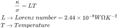
The law defines the ratio of the electronic role of the thermal conductivity of a material to the electrical conductivity of a material (metal) is directly relative to the temperature.This law is named after Gustav Wiedemann and Rudolph Franz in 1853 reported that the ratio  has more or less the similar value for dissimilar metal at the same temperature.

Derivation of the Law

For that, we have to assume a homogeneous isotropic material. This material is then subjected to a temperature gradient . The direction of the heat flow will be opposite to that of the temperature gradient all the way through the conducting medium.
The heat flowing through the material per unit time per unit area is the heat flux. It will be proportional to the temperature gradient.K → Coefficient of thermal conductivity (W/mK)
K = Kphonon + Kelectron ; since the transfer of heat in solids owing to phonon and electron.
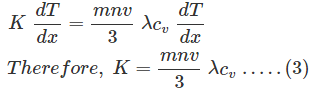
Now, we can derive the expression for coefficient of thermal conductivity.
For that, we have to assume the flow of heat is from higher temperature to lower temperature in a metal slab which has a temperature gradient of .cv → Specific heat
n → Number of particles per unit volume
λ → mean free path of collisions
v → velocity of electrons
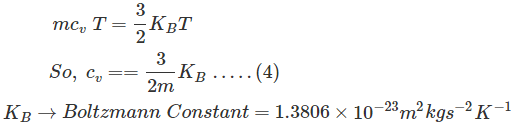
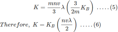
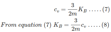
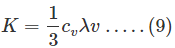
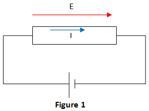
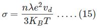
Comparing the equations (1) and (2), we getWe know that the energy of free electrons isWe put the equation (4) in (3)Now, the specific heat for an ideal gas at constant volume,When we put equation (8) in (6), we getNext, we can consider the electrical current density of a metal with the application of electric field, E (figure 1)
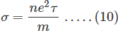
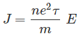
J = σ E ; Ohms lawwiedemann franz lawSo, the correct form of Ohms law is given byThere is a mean free path and mean time between the collisions.e → Charge of the electron = 1.602 × 10⁻⁹ C
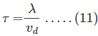
τ → Collision time or mean time: It is the average time for the electron to move or travel prior to scattering.
vd → Drift Velocity: It is the standard velocity of the electron during the collision time.
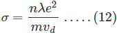
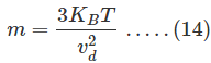
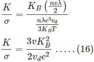
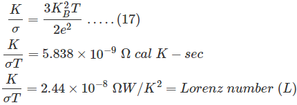
When we put equation (11) in (10), we get electrical conductivity (Drude Conductivity) asConsider the electrons which move in a metal without any application of electrical field. Then the equipartition theorem is given byFrom equation (13) we get m asNow, we put equation (14) in (12)Thus, we got the values of K and σ from equation (6) and (15). Now, we can take the ratio We assume v = vd, then equation (16) becomesFrom this, we can say that the ratio  is similar for all the metals. It is also a function of temperature. This law is known as Wiedemann-Franz Lorenz Law. We can conclude that the most excellent electrical conductor will be a best thermal conductor.

Limitations of Wiedemann Franz Law

  • The value of L is not the same for all the materials.
  • This law is not valid for intermediate temperature.
  • In the pure metals, both σ and κ increases as temperature decreases.