SOLAR ENERGY EDUCATION
Solar power is clean green electricity that is either created from sunlight or from heat from the sun. Having solar electricity in your home usually means setting up a solar photovoltaic system on your roof.
Definition of photovoltaic: Photo = “light” and photons = energy particles coming from sunlight; voltaic = producing a voltage or volts. Abbreviation = PV
Solar energy is a renewable free source of energy that is sustainable and totally inexhaustible, unlike fossil fuels which are finite. It is also a non-polluting source of energy and it does not emit any greenhouse gases when producing electricity. The solar electricity that is produced can supply your entire or partial energy consumption.
New! Solar education for kids and teens
We’ve put together a page geared more towards older primary school and secondary school age children covering the basics of solar power; plus a basic calculator so kids can see how many solar panels would be needed to power their home.
We’ve put together a page geared more towards older primary school and secondary school age children covering the basics of solar power; plus a basic calculator so kids can see how many solar panels would be needed to power their home.
Solar Workshop video series
How a solar panel is made
A solar panel, while rugged and durable in its finished form, requires a complex and very technical process in its production.
In traditional solar modules (polycrystalline and monocrystalline), silicon wafers are impregnated with impurities to create a semiconductor that converts sunlight into electric current. Electrical contacts are then created to join one solar cell to another. As silicon reflects, an anti-reflective coating is placed on top of the silicon wafers, usually titanium dioxide or silicon oxide.
The solar cells are laid between a superstrate layer on the top and a backsheet layer on the bottom. The superstrate is usually glass, and the backsheet is plastic. This is then placed inside an aluminium frame to create a finished solar panel
In thin film solar panels, it’s a different process. It begins with a thin layer of flexible substrate such as coated glass, stainless steel or plastic and metal contact, and the solar cell is then built up in a series of layers. An oxide layer is then applied at the end to form the electrical contact of the cell. The cell is then laminated with a weather resistant superstrate material.
The following is a brief video on how a solar panel is made:
Using solar power means reducing your energy bills and saving money. Also, installing solar PV panels adds value to your home. They are low maintenance and unobtrusive. Read our 10 tips for getting a solar power system, or tips for choosing solar panels.
How does a solar panel work?
As touched on earlier, solar panels use what’s known as the photovoltaic effect to generate power. This is the process by which light is converted to energy at the atomic level.
Put simply; when light hits a solar cell, electrons are knocked loose from a solar cell’s semiconductor material atoms. Positive and negative electrical conductors associated with each solar cell form a circuit that capture this energy in the form of an electrical current.
Solar electricity
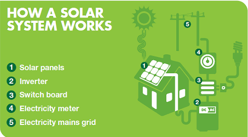
Electricity travels from a power plant to your house via a power grid. This main grid is the national electricity grid found in QLD, NSW, VIC, SA, TAS, NT and WA. If you are not connected to the grid it means that the power lines do not reach your house, usually because you live in a remote area. The power that is supplied to the grid is most often produced by coal-fired power plants, which pollute the environment by releasing tonnes of greenhouse gases.
PV systems generate energy from sunlight during the day. This energy goes into a grid connect inverter which converts the DC current into AC current, similar to that of the grid. This solar electricity current can then power all the appliances in your home, such as cooking appliances, phones, computers, lights, radios, etc… Power can be drawn directly from the solar inverter and any leftover electricity can then be fed back into the grid.
 If you need to use more electricity than what is produced by your grid connected solar system, that power will simply be taken from the main distribution grid. On the other hand, if you produce more energy than what you use, then you are credited for the surplus on your electricity bill. Some electricity retailers offer net billing, meaning your supplier buys the excess power you produce for the same retail price they charge you.
Grid connect systems differ from stand alone solar power systems as they eliminate the need for a battery back-up. At night or during cloudy weather you can draw electricity directly from the grid. To install a grid connect solar PV system, you need sufficient space on your north-facing roof.
… more information about grid connected solar power systems.
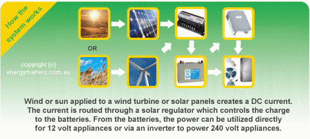
A stand alone solar system means that you are not connected to the public grid. When you are “off grid” it means that you must create your own electricity to run your home. In this case, solar panels or wind turbines are used to charge batteries which store energy.
 Often batteries are connected to an inverter which supplies 240V AC power to run most appliances in a standard house. An inverter is not required for stand alone systems that run DC appliances.
… more information about off grid solar power systems.
Solar PV pumping systems are used for irrigation and drinking water in places where there is no mains power available. Solar PV water pumps make an ideal replacement for diesel and petrol powered pumps as they deliver the most water when it is needed, i.e. when the sun is shining. They also emit no greenhouse gas and last a very long time. Essentially, any DC pump could be converted to a solar pump with the correct controller.
… more information about solar pumping.
Solar thermal applications are the most widely used category of solar energy technology. These technologies use heat from the sun for water and space heating, ventilation, and many other applications.
Heating water represents the biggest single source of greenhouse gas emissions in an average Australian household (if you don’t count the car). The Australian government is encouraging households to switch to sustainable hot water technologies by introducing financial rebates. The rebates aim to reward homes for replacing traditional hot-water heaters with clean energy hot-water like solar and solar thermal hot water storage systems. Home owners can save up to 75% on their water heating bills with a solar hot water system.
Solar hot water technology is entirely different to the technology that you see when you think of the basic solar PV panels on the roof of a house. Solar hot water systems are usually composed of a solar collector and a tank.
There are two types of collectors:
- evacuated tubes, and
- flat plate collectors
As heat rises, the hot water delivered to the tank from the solar collectors is drawn from the top for use in the house
Electricity travels from a power plant to your house via a power grid. This main grid is the national electricity grid found in QLD, NSW, VIC, SA, TAS, NT and WA. If you are not connected to the grid it means that the power lines do not reach your house, usually because you live in a remote area. The power that is supplied to the grid is most often produced by coal-fired power plants, which pollute the environment by releasing tonnes of greenhouse gases.
PV systems generate energy from sunlight during the day. This energy goes into a grid connect inverter which converts the DC current into AC current, similar to that of the grid. This solar electricity current can then power all the appliances in your home, such as cooking appliances, phones, computers, lights, radios, etc… Power can be drawn directly from the solar inverter and any leftover electricity can then be fed back into the grid.

If you need to use more electricity than what is produced by your grid connected solar system, that power will simply be taken from the main distribution grid. On the other hand, if you produce more energy than what you use, then you are credited for the surplus on your electricity bill. Some electricity retailers offer net billing, meaning your supplier buys the excess power you produce for the same retail price they charge you.
Grid connect systems differ from stand alone solar power systems as they eliminate the need for a battery back-up. At night or during cloudy weather you can draw electricity directly from the grid. To install a grid connect solar PV system, you need sufficient space on your north-facing roof.
… more information about grid connected solar power systems.
A stand alone solar system means that you are not connected to the public grid. When you are “off grid” it means that you must create your own electricity to run your home. In this case, solar panels or wind turbines are used to charge batteries which store energy.

Often batteries are connected to an inverter which supplies 240V AC power to run most appliances in a standard house. An inverter is not required for stand alone systems that run DC appliances.
… more information about off grid solar power systems.
Solar PV pumping systems are used for irrigation and drinking water in places where there is no mains power available. Solar PV water pumps make an ideal replacement for diesel and petrol powered pumps as they deliver the most water when it is needed, i.e. when the sun is shining. They also emit no greenhouse gas and last a very long time. Essentially, any DC pump could be converted to a solar pump with the correct controller.
… more information about solar pumping.
Solar thermal applications are the most widely used category of solar energy technology. These technologies use heat from the sun for water and space heating, ventilation, and many other applications.
Heating water represents the biggest single source of greenhouse gas emissions in an average Australian household (if you don’t count the car). The Australian government is encouraging households to switch to sustainable hot water technologies by introducing financial rebates. The rebates aim to reward homes for replacing traditional hot-water heaters with clean energy hot-water like solar and solar thermal hot water storage systems. Home owners can save up to 75% on their water heating bills with a solar hot water system.
Solar hot water technology is entirely different to the technology that you see when you think of the basic solar PV panels on the roof of a house. Solar hot water systems are usually composed of a solar collector and a tank.
There are two types of collectors:
- evacuated tubes, and
- flat plate collectors
As heat rises, the hot water delivered to the tank from the solar collectors is drawn from the top for use in the house


 A . 0 = 0 where A can be either 0 or 1.


 In an transformer primary winding and secondary windings are coupled with a low reluctance ferromagnetic core. The core is used in an electrical transforme for confining