Sunday, 5 November 2017

Boolean Algebra Theorems and Laws of Boolean Algebra

Boolean algebra is a different kind of algebra or rather can be said a new kind of algebra which was invented by world famous mathematician George Boole in the year of 1854. He published it in his book “An Investigation of the Laws of Thought”. Later using this technique Claude Shannon introduced a new type of algebra which is termed as Switching Algebra. In digital electronics there are several methods of simplifying the design of logic circuits. This algebra is one of these methods. According to George Boole symbols can be used to represent the structure of logical thoughts. This type of algebra deals with the rules or laws, which are known as laws of Boolean algebra by which the logical operations are carried out.

There are also few theorems of Boolean algebra, that are needed to be noticed carefully because these make calculation fastest and easier. Boolean logic deals with only two variables, 1 and 0 by which all the mathematical operations are to be performed.
Boolean algebra or switching algebra is a system of mathematical logic to perform different mathematical operations in binary system. There only three basis binary operations, AND, OR and NOT by which all simple as well as complex binary mathematical operations are to be done. There are many rules in Boolean algebra by which those mathematical operations are done. In Boolean algebra, the variables are represented by English Capital Letter like A, B, C etc and the value of each variable can be either 1 or 0, nothing else. In Boolean algebra an expression given can also be converted into a logic diagram using different logic gates like AND gateOR gate and NOT gateNOR gatesNAND gatesXOR gatesXNOR gates etc.
Some basic logical Boolean operations, AND OperationOR OperationNot OperationSome basic laws for Boolean AlgebraA . 0 = 0 where A can be either 0 or 1.
A . 1 = A where A can be either 0 or 1.
A . A = A where A can be either 0 or 1.
A . Ā = 0 where A can be either 0 or 1.
A + 0 = A where A can be either 0 or 1.
A + 1 = 1 where A can be either 0 or 1.
A + Ā = 1
A + A = A
A + B = B + A where A and B can be either 0 or 1.
A . B = B . A where A and B can be either 0 or 1.
The laws of Boolean algebra are also true for more than two variables like,

Cumulative Law for Boolean Algebra

cumulative laws for boolean algebraAccording to Cumulative Law, the order of OR operations and AND operations conducted on the variables makes no differences.

Associative Laws for Boolean Algebra

This law is for several variables, where the OR operation of the variables result is same though the grouping of the variables. This law is quite same in case of AND operators.associative laws for boolean algebra

Distributive Laws for Boolean Algebra

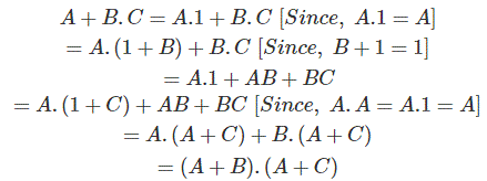
This law is composed of two operators, AND and OR.distributive laws for boolean algebraLet us show one use of this law to prove the expressionProof:

Redundant Literal Rule

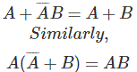
redundant literal ruleFrom truth table,
InputsOutput
ABĀBA + ĀB
0000
0111
1001
1101
InputsOutput
ABA+B
000
011
101
111
From truth table it is proved that,

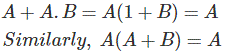
Absorption Laws for Boolean Algebra

Proof from truth table,
InputsOutput
ABABA+A.B
0000
0100
1001
1111
Both A and A+A.B column is same.Proof from truth table,
ABA+BA.X(A+B)
0000
0110
1011
1111
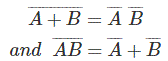
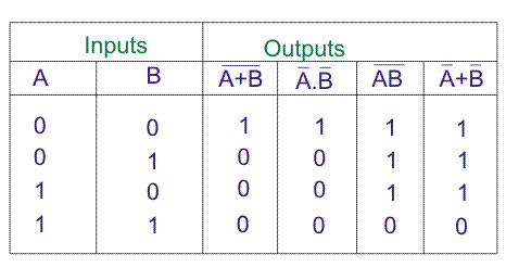
Both A and A.X or A(A+B) column are same.De Morgan’s Therem,Proof from truth table,

Examples of Boolean Algebra

These are another method of simplifying complex Boolean expression. In this method we only use three simple steps.
  1. Complement entire Boolean expression.
  2. Change all ORs to ANDs and all ANDs to ORs.
  3. Now, complement each of the variable and get final expression.
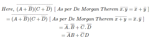
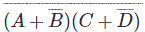
By this method, will be first complemented, i.e..Now, change all (+) to (.) and (.) to (+) i.e.Now, complement each of the variable,This is the final simplified form of Boolean expression,And it is exactly equal to the results which have been come by applying De Morgan Theorem.
Another example,By Second Method,Representation of Boolean function in truth table.

Let us consider a Boolean function,Now let us represent the function in truth table.Thus we have shown some basic laws of Boolean algebra. In the other page we have described De Morgan’s theorems and related laws on it.

Digital Electronics

We know there are two types of signals, one is analog or continuous signal and the second one is Digital or discrete signal. So the science or field of research in the area of engineering is termed as Analog and Digital Electronics respectively. Now coming to the area of Digital Electronics, it is essential to understand wide range of applications from industrial electronics to the fields of communication, from micro embedded systems to military equipment. The main and perhaps the most revolutionary advantage of digital electronics is the decrease in size and the improvement in technology.
We have chosen to discuss various topics of Digital Electronics from the very fundamentals of this subject such as Number systems, logic circuits going deep into those topics, like discussing various types of number systems, which we should use and how, inter relation among those number systems to the somewhat tougher concepts of Digital Electronics like TTLPMOS-NMOS logic, Flip Flops etc. to get an idea about the whole subject.
All the topics of the related articles have been amply presented by diagrams, designs, tables and examples to make every topic understandable as much as possible. The topics are written in such a manner that if one go through them he will grasp the very basic idea at first attempt and further reading will enhance the technical knowledge.
Now let us inform you what we have included in the topics of Digital Electronics, as we have already discussed we have started from the very basic topics of Digital Electronics like Number system. Then we have discussed the extension of number system like various types of number system, interrelation among different types of number systems making oneself absolutely comfortable with the fundamentals of Number system. Then we have enlightened the very important field of Digital Electronics i.e. Binary Arithmetic and Boolean algebra. And we have discussed about them in elaborated manner. From binary additionbinary subtractionbinary multiplication and binary division to the basics of Boolean algebra.
After that we have written topics about various types of codes such as ASCII codeGray CodeHamming code which have made the input output format very easy. Then various types of logic gates (AND gateOR gateNOT gateNAND gateNOR gateEX-OR gate) have been discussed in an elaborated manner with diagrams, explanations and truth tables to make each one of them very easy to understand.
These may be classified as the fundamentals of Digital Electronics without which the subject cannot be understood at all. So after discussing about them we have gone deep into the subject. Topics like TTL, Logic Families, various MOS gates, Flip Flops (J-K, D, T etc.) have been discussed.
The sole purpose of introducing this subject in our Electrical Engineering website is because now days all the engineering streams are interrelated and the knowledge of Digital Electronics is very much essential for an electrical Engineer and we have tried our best to make oneself familiar with the subject technically as much as possible.

Air Core Transformer

If an alternating current is supplied to a coil, an alternating magnetic field is produced surrounding it. If another coil is brought inside this magnetic field, an alternating emf is induced across the second coil also as per Faraday's law of electromagnetic induction. This induced emf in the second coil can be utilized to feed a load. As in this example the flux is linked with both coils through air, so this arrangement can be referred as air core transformer. Here, first coil serves as primary winding and second coil serves as secondary winding of the said transformer. Whenever there is a need of changing voltage level from one level to another in power network we use an electrical transformer.principle of transformerWhenever there is a need of electrical isolation from one circuit to other, we use transformer.For transforming current and voltage to low measurable level we use current transformer and potential transformer respectively. These are not only the applications of transformers.
Electrical transformers are also used for many different purposes. In different electronics applications smaller sized transformers are used. Examples of these transformers are air core transformer, audio frequency transformer etc. These are referred as special purpose transformers and simply called special transformer. Construction wise they are different from general power transformer but basic working principle is same as all other transformers. That means in this case, the working principle of transformer is also based on mutual inductionbetween two magnetically linked windings. Here we will discuss about air core transformers.air core transformerIn an transformer primary winding and secondary windings are coupled with a low reluctance ferromagnetic core. The core is used in an electrical transforme for confining magnetic fluxand facilitating maximum flux linkage between primary and secondary winding. Laminated steel sheets are used to construct the core of transformer. But, ferromagnetic materials like steel as core of transformer, suffers from hysteresis losseddy current losses. Also it faces problem of getting saturated after certain level of magnetization. But these can be avoided in air core transformer as ferromagnetic core is absent in this transformer.
In very high frequency applications, distortion in electromagnetic field should be avoided otherwise there may be a significant affect in output signal. So for maintaining quality of signal it is desired to avoid any noise or distortion in the signal. As ferromagnetic material causes noise or distortion in the signal, it should be avoided in high frequency application like signal transmission. Thus air core transformer is introduced, in the application of high frequency radio transmission. Here iron core of transformer is absent and the flux is linked with the windings through air. In addition to the noise-free operation, an air core transformer is quite light weight due to absence of heavy weight iron core. That is why this type of transformer is most suitable for portable, light weight electronic devices and high frequency devices. Air core transformers are are generally used in radio transmitter and communication devices etc.

Construction of Air Core Transformer

The coils of insulated copper wire, are wound on a plastic tube or cardboard etc. There are mainly two forms of air core transformer. One is cylindrical form and other is toroidal form. In cylindrical form of air transformer, insulated copper wires are wound on a non metallic cylindrical structure. This non metallic hollow structure gives the winding necessary mechanical support. The copper winding wounded around the non metallic cylinder is tapped at different points as necessary. The secondary supply is taken across these taps. Sometimes capacitor is connected to the winding to maintain the constant resonance of the tuning circuit. The flux flows through the air surrounding the winding and air inside hollow cylinder. For proper impedance matching, sometime a guard winding is wound surrounding the main copper winding. This guard winding is further connected with antenna receivers or grounded properly.
On the other hand in toroidal form of air core transformer, insulated copper wires are wound around a ring of hard plastic or other non metallic substance. Actually, the wire is wound in circular way around the periphery of the ring. This type of transformers are only used in very high frequency applications. In this case the winding is not tapped, here two separate windings are used for primary and secondary purpose. Therefore, the effect of stray coupling is minimized in toroidal air core transformer. The primary is to secondary ratio of windings varies and it depends upon the frequency range and the type of operation.

Dry Type Transformer

What is Dry Type Transformer?

Dry type transformer never uses any insulating liquid where its winding with core be immerged. Rather windings with core are kept within a sealed tank that is pressurized with air.

Type of Dry Type Transformer

The dry type transformer is of two types. They are
  1. Cast Resin Dry Type Transformer ( CRT)
  2. Vacuum pressure Impregnated Transformer ( VPI)

Cast Resin Dry Type Transformer ( CRT)

Cast resin dry type transformer (CRT) is used in the high moisture prone areas. It is because of its primary and secondary windings are encapsulated with epoxy resin. This encapsulation helps to prevent moisture to penetrate to affect the winding material. Complete protection is achieved by this cast resin encapsulation so that the transformer can work without disruption in highly moisture prone area. Thus this transformer is non hygroscopic.
This type of transformer is available in ratings of 25 KVA to 12,500 KVA. with insulation class of F (90oC Temp. Rise).
This type of transformer has some featured advantages. They are-
  1. Better over load capacity.
  2. Low partial discharge along with low loss. Hence efficiency is very good.
  3. As it is with non inflammable winding insulation, it offers zero risk to fire hazard. So it is suitable for indoor installation.
  4. Can be fitted outdoor in IP 45 enclosure.
  5. And off course non hygroscopic.

Vacuum Pressure Impregnated Transformer (VPI)

This type of transformer is made with minimum flammable material as insulation of windings. The windings of this transformer are made in foil or strip in a continuous layer. But for higher voltages, the winding is made of disks that are connected in series or parallel as per power rating with respect to voltage level.
The insulation of the winding is void free impregnation that is made with class H polyester resin. The primary and secondary winding with core are laced safely within a vacuum protective box. Moisture Ingress Protection is high and it never gets affected by moisture.
This type of transformer is available from 5KVA to 30MVA with insulation grade F(155oC) and H(180oC). It’s with Protection up to IP56.
This type of transformer has several advantages. They are-
  1. High mechanical strength.
  2. Void free insulation.
  3. No temperature fluctuation.
  4. Easy maintenance.
  5. Less prone to fire hazard.

Advantages of Dry Type Transformer

The main advantages of dry type transformer are given below.
  • Safety for people and property.
  • Maintenance and pollution-free solution.
  • Easy installation.
  • Side clearance is less.
  • Environmentally friendly.
  • Excellent capacity to support overloads.
  • Reduced cost on civil installation works and fire protection systems.
  • Excellent performance in case of seismic events.
  • No fire hazard.
  • Excellent resistance to short circuit currents.
  • Long lasting due to low thermal and dielectric heating.
  • Suited for damp and contaminated areas.

Disadvantages of Dry Type Transformer

But there are some disadvantages of dry type transformer. They are-
  • Dry type transformer is long lasting and with less chance of winding failure. But once it fails whole set up is to changed, i.e. complete change of high voltage and low voltage winding with limb.
  • For same power and voltage rating, dry type transformer is costlier than oil cooled transformer.

Application of Dry Type Transformer

Dry type transformer are widely used in-
  • Chemical, oil and gas industry
  • Environmentally sensitive areas (e.g. water protection areas)
  • Fire-risk areas (e.g. forests)
  • Inner-city substations
  • Indoor and underground substations
  • Renewable generation (e.g. off-shore wind turbines)

Important Factors to Design a Dry Type Transformer

The important design parameters for a dry type transformer are given below.
Choice of Insulation Type
Generally F and H class of insulation of insulation is used to insulate the primary and secondary winding. It is because these classes have high temperature withstand property, i.e. 155oC for F and 180oC for H class of insulation. Generally varnish and polyester resin are used as insulation of the winding. Apart from the temperature withstand capability, mechanical strength; dielectric strength and resistance to thermal shock are the basic capabilities that have to be fulfilled by the insulation selected for the windings.
Selection of Winding Material
Generally copper and aluminum are used to make the winding or coil. Though copper is better conductor, aluminum conductor wound transformer possesses low cost and weight. For the same current rating, copper conductor with less cross section is used as the winding material in the transformer. Copper coil provides more mechanical strength than aluminum coil.
Selection of Core Material with Low Hysteresis Loss
Core material selection is very important in transformer design. Core material must possess high permeability and less hysteresis loss. But both cannot be achieved in any core material. Generally silicon steel, CRGO etc are used to allow minimum hysteresis loss with higher permeability.
Regulation
When transformer secondary voltage drops abruptly due to increase in load, this regulation is called poor regulation. Poor regulation is due to transformer higher internal leakage reactance. So, leakage reactance is kept within 2% during design.
Life Expectancy
Life of the transformer depends on the breakdown of winding insulation due to temperature rising effect in winding due to overloading. Normally class B, F and H insulation is preferred for dry type transformer to withstand higher temperature gradient including ambient temperature. So design of the transformer must be done with respect to the rise of the temperature of operating full load condition.
Losses
No load losses mean core loss and eddy current that is independent of loading condition. But in loading condition copper loss occurs that includes the iron loss to increase the value of voltage regulation, i.e. poor voltage regulation. Leakage reactance and winding resistance must be within moderate value to minimize this loss and better voltage regulation, thus higher efficiency.
Overloading
Over loading condition is harmful for transformer for long time span. Overloading is the cause of overheating when transformer has to fulfill its connected load demand. Hence huge amount of current makes copper loss in the winding, and that causes transformer damage. To cool the winding, fan-cooling system is provided in dry type transformer.
K-factor
It is the ability of withstanding of heat generated by non sinusoidal current in the transformer winding. Pure sine wave is not obtained in voltage and current wave form. It is due to today’s various electronic devices uses. Several harmonics are present in the voltage and current wave form. Robust design of a transformer off course bothers k-factor to provide transformer long lasting life.
Insulation Level
In transformer design, insulation level adjustment is an important factor. Generally insulation level is chosen as per basic impulse level and system over voltage. Strong insulation level increases the life of a transformer.

Distribution Transformer | All Day Efficiency of Distribution Transformer

Distribution Transformer

The step down transformers used for electric power distribution purpose are referred as distribution transformer. There are several types of transformer used in the distribution system. Such as single phase transformer, three phase transformer, pole mounted transformer, pad mounted transformer, and underground transformer. Distribution transformers are generally small in size and filled with insulating oil. These transformers are available in the market in various sizes and efficiencies. Selection of distribution transformer depends upon the purpose and budget of the end users.

Secondary Terminals of Distribution Transformer

Secondary terminals of distribution transformer deliver electrical power at a utilization voltage level to the consumer end via energy metering system.
In case of three phase distribution system three phase four wire secondary systems are adopted. Here, three phases, which means red, yellow and blue phase conductors, come out from three low voltage bushing studs of the transformer. The neutral wire is connected to the fourth bushing which is also referred as a neutral bushing of the transformer.distribution transformerThe neutral point of the distribution transformer is projected from the tie point of 3–phase winding inside the transformer. In case of industrial heavy three phase load, four wire system is directly delivered to the consumer end, but in case of single phase light load, one phase and neutral connection of the three phase distribution transformer, are connected to the consumer’s energy meter.distribution transformerThe secondary terminals of distribution transformer at first is connected to the three phase bus of distribution kiosk, located nearby the transformer. This connection is essentially made via a fuse unit to provide protection from external fault to the transformer. From this three phase bus in the distribution kiosk, different, three phase or single phase service mains or sub distributors are connected.
A typical type of-single phase system is available in United State of America for supplying single phase residential tons. Here, single phase pole mounted transformer is used for supplying single phase residential load. This type pole mounted transformer has total three secondary terminals, one of which is ground and other two are phase terminals. Two phase wires provide 240 volts across them, and the voltage across any of the phase wire and the ground wire is 120 volts. So a consumer can be supplied either of 240 volts or 120 volts supply depending upon his requirement. Actually in this system, the secondary winding of the distribution transformer is center tapped. The center wire is grounded and marked as neutral. The two end conductors of the winding is called hot wire.

Efficiency of Distribution Transformer

The efficiency of distribution transformer is defined as the ratio between output power to input power of the transformer at full load condition, but in case of a distribution transformer, the concept is a little bit different as the possibility of running a distribution transformer at its full load condition is nearly nil. The efficiency of the transformer is maximum at 50% of full load.
A transformer has mainly two types of losses, these are, iron losses and copper losses. Iron loss, which is also referred as core loss, consists of hysteresis loss and eddy current loss. These two losses are constant when the transformer is charged. That means the amount of these losses does not depend upon the condition of secondary load of the transformer. In all loading condition, these are fixed. But the copper loss which is also referred as I2R loss entirely depends upon load I. A distribution transformer cannot be run with constant load throughout 24 hours. At day peak time it’s loading is high, whereas in night lean time its loading may be negligible. So selecting a transformer depending upon its conventional efficiency is not practical and economical, too. As a solution of these problems, the concept of all day efficiency of distribution transformer came into the picture. So this efficiency is same as the efficiency of distribution transformer. In this concept, we use the ratio of total energy delivered by the transformer to the total energy fed to the transformer, during a 24 hrs span of time instead of ratio of power output and input of the transformer. Hence, all day efficiency is determined as, total KWh at the secondary to the total KWh at the primary of the transformer for a long specific time period preferably 24 hrs. i.e,
This is very much useful to judge the performance of a distribution transformer, whose primary is connected to the system forever, but secondary load varies tremendously throughout the day.

High Voltage Transformer

Such transformers are normally used in high voltage laboratory for testing purpose. This transformer is subjected to transient voltages and surges during their normal operation when the insulation under test breaks down. To withstand these impulse voltages, the insulation of transformer is carefully designed. This high voltage transformer is single phase, core type. This type of transformer is generally oil immersed. Bakelite sheets are used for separating high tension and low tension winding. The high voltage transformers used for HT cable testing purpose are to supply also sufficient electric current and that is why the cooling system of these transformers is very carefully designed. Special cares also to be taken for voltage regulation of transformers.
For insulator testing purposes, the required current is very less but, while the insulator breaks down during testing, there would flow huge current through the transformer. To limit this current, a high resistance is connected in series with transformer. As the current required is very less during insulation testing, this high voltage transformer needs not to have high KVA ratings. The table below shows, the rating of transformer used for various testing purposes. Up to voltage 500 KV, generally single unit of high voltage transformer is used. But for higher voltage rating more than one transformer, are connected in cascade to produce required high voltage. Actually for getting such high voltage, a single transformer has to be very huge in size which is not at all economical.
The figure below shows the typical cascading connection of two transformers.Cascade TransformerLow voltage is supplied to the low voltage winding of a step up transformer 1 as shown in the figure below. The tank of this transformer is earthed. The secondary of this transformer, is connected to the earthed tank and other end comes out through a high voltage bushing. The bushing is so specially designed and manufactured, that it can withstand full secondary high voltage, in respect of earthed potential of transformer tank. Another tapping terminal also runs through this high voltage bushing. The high voltage end and tapping terminal ends are connected across primary of the second transformer. One end of the secondary winding of second transformer is connected to its tank. The tank of second transformer is not earthed like first transformer. This is isolated and insulated from earth for full secondary voltage of the transformer. One end of the high voltage or secondary winding of second transformer is connected to the earth and other end alone comes out from the high voltage bushing for feeding high voltage to the equipments and insulators under testing.
SLPurposesCapacityMaximum Voltage
1.Routine test for electric motors & switch gearssmall2 to 3 KV
2.Insulation testing10 to 20 KVA50 KV
3.Routine test of cable50 KVA10 to 30 KV
4.Extra high voltage transformer & insulators testing20 to 50 KVA100 – 200 KV
5.String insulator testing0.5 to 1 KVA per KV500 to 2000 KV
6.High voltage cable testing100 to 500 KVA100 to 500 KV

Voltage Regulation

The surges on the high voltage side of the transformer should be avoided. Also for accuracy of voltage measurement, the voltage regulation of transformer should be smooth enough. Sudden variation of voltage during test also to be avoided. A voltage regulator should not distort the voltage wave form during testing.
The output voltage of high voltage transformer is regulated by changing input voltage to the primary side.
This variation of input voltage to the primary can be done either by
  1. Variation of alternator field current.
  2. Inserting resistance or inductance in the supply circuit from alternator.
  3. Using induction regulator.
  4. Using tapped transformer.

Variation of Alternator Field Current

If one single alternator is used to supply power to the high voltage transformer, the method of variation of alternator field current can be performed. An alternator gives sinusoidal wave form of voltage at no load. But it is also desirable, that, this voltage waveform should not be distorted under load condition. This is achieved by making larger air gap between stator and rotor and by special design of armature winding of alternator.Alternator Field ControlFor regulating voltage, no impedance is required to be connected in series with the primary of the transformer, in this case. So voltage wave form distortion due to inserted impedance can be avoided in voltage regulation with variation of alternator field current. The field current of the alternator is varied by a voltage divider, connected across DC supply to the field. In this method zero voltage can be achieved by neutralizing residual magnetism of field by severing required field current.

Voltage Regulation by Inserting Resistance or Inductance

When there is no provision of using separate alternator for high voltage testing in the lab, this method is applied. The high voltage transformer is fed from AC supply mains in case of testing of small equipments. The variation of supply voltage to the H. V. transformer is obtained by inserting resistance in series with the AC supply. A sliding >resistance is most suitable for achieving smooth regulation of voltage supplied to the transformer primary. Sometimes the resistance can also be connected across main supply and used as voltage divider, to supply variable voltage to the transformer.potential divider controlThis method is quite simple but it suffers from power loss problem. The power loss across the resistance is not practically accepted for high power tests. The resistance required for high power application is quite large in size and also not cost effective. Because of these disadvantages this method is limited upto the application for the equipment rated from 2 KVA to 3 KVA.
Instead of resistance, voltage regulation can be achieved by connecting a choke coil (inductor) in series with the primary of the transformer. Voltage variation can be obtained by changing the position of iron core in the choke coil. That means, by inserting and withdrawing iron core inside the coil, the voltage variation is achieved. Due to lower power loss, this method is more efficient than resistance method. But still it has some inherent disadvantages.
  1. For higher power, very large size of this choke coil is required.
  2. There is always a good chance of voltage distortion due to iron core in the coil.
  3. Another disadvantage of this method, is in fact that increase of its inductance will increase the primary voltage of the transformer instead of decreasing it if the power factor of the load on the secondary side of the testing transformer is leading as is often the case.

Induction Regulator Method

Inductance regulator control is suitable for all ranges of power. It can be efficiently used for all load and power factors. Smooth voltage regulation from zero to full range can be achieved by this method.In induction regulator is essentially a variable transformer. The secondary voltage of this variable transformer can be varied by changing primary turns. Variation of primary turns is achieved by rotating a knob attached to the transformer. Actually in this type of variable transformer, the number of turns in primary and secondary windings are same. But when we rotate the said knob attached to the transformer the number of active turns across primary varies, hence turns ratio changes which ultimately results to variable secondary voltage.
During designing this type of transformer it must be kept in mind that, the winding of transformer on rotor portion are so designed and distributed that, it does not distort the actual wave form of the test voltage.
Induction regulator method is most suitable for the high voltage transformer, used for power cable testing purpose. Because its gradual voltage variation at loads of any magnitude is advantageous for such work.
inductor regulator

Voltage Variation by Means of Tapped Transformer

In this method of voltage regulation of transformer, a tapped transformer is essentially used. The theory of voltage variation by tapped transformer is quite simple.
In this arrangement the primary of transformer is connected with LT supply main. The secondary winding of the transformer is tapped at various points. The voltage at primary of HT transformer is supplied from these tapped points.
When the contact of tapping switch moves from one tap to another, these would be a chance of opening the secondary circuit of tapping transformer. Due to this opening there may be a high chance of surge in the high voltage transformer.
To avoid this situation two contact brushes are used for tap changer switch. It makes contact with adjacent studs and with a buffer resistance or reactance coil between them to prevent short circuit of a section of the transformer winding.
Here in the diagram we have shown a two winding transformer as tapped transformer but it can be a auto transformer too. For gradual regulation a number of course tapping are used together with fine tappings. This method of voltage regulation by tapped transformer is advantageous for its high efficiency and small wave form distortion as there is no voltage drops in the circuit, only the voltage wave is stepped up.
As the winding is tapped the voltage regulation is not very smooth. But it can be made smoother by using very large number of taps in the secondary winding of tapped transformer but it increases cost of the transformer.
Hence this method of voltage regulation is used on high voltage transformer only when it is required for large and expensive switchgear testing.Tapped Transformer Regulator